 ENTSO-E
Line-commutated Converters (LCC)
Overview
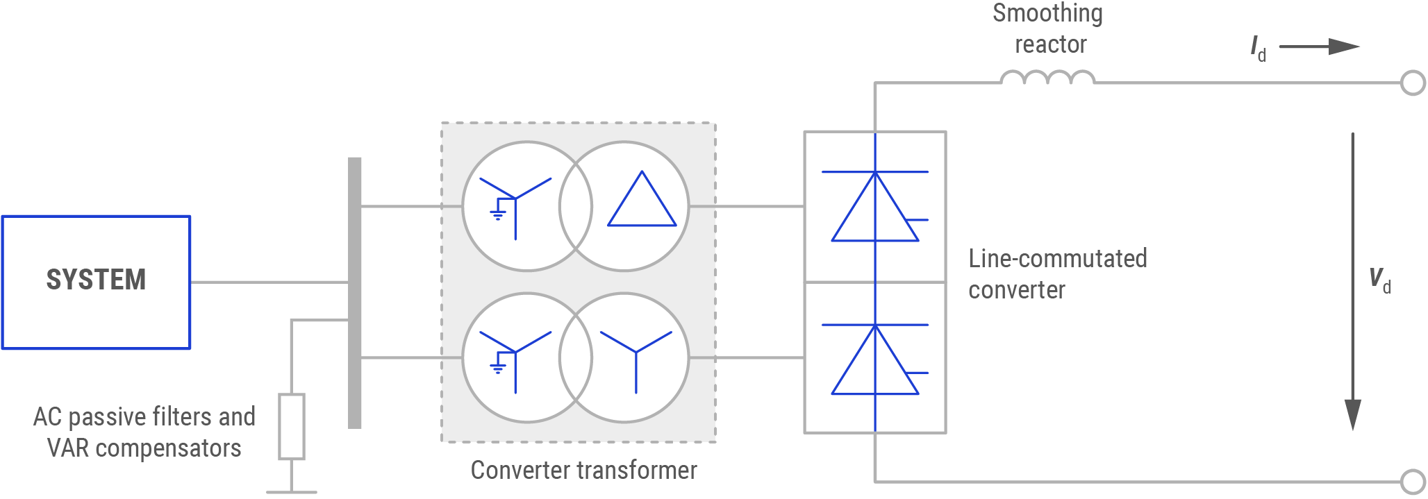
Line-commutated converters (LCCs) are the conventional, mature and well-established technology used to convert electric power from Alternating Current (AC) to Direct Current (DC) or vice versa. The term line-commutated indicates that the conversion process relies on a stable line voltage, with clear zero-crossings of the AC system to which the converter is connected to have a flow commutation from one switching element to another.
In a current source converter (CSC), the DC current is kept constant with a small ripple using a large inductor. In practice, for most applications an LCC equals an CSC. The direction of power flow through a CSC is determined by the polarity of the DC voltage, whereas the direction of current flow remains the same.
Technology Types
LCCs are differentiated in two technology types: Mercury-arc valves-based LCC and Thyristor-based LCC.
- Mercury-arc valves based LCCs is a technology that was used until the 1970s. It is a type of cold cathode gas-filled tube made from a pool of liquid mercury. It was therefore self-restoring and long-lasting, capable of carrying high currents up to 1.8 kA at 450 kV but with high maintenance time and serious environmental hazard risks. The last operating mercury arc system was shut down in 2012.
- Thyristors-based LCCs were first used in High Voltage Direct Current (HVDC) systems in the early 1970s while being widely implemented since the 1960s, for both overhead lines (OHLs) and cable applications. A thyristor is a solid-state semiconductor device similar to the diode, but with an extra control terminal that is used to switch the device on at a defined instant. Additional passive components (e.g. grading capacitors and resistors) need to be connected in parallel with each thyristor to ensure a uniform share of the voltage between the thyristors across the valve. Initial designs used six pulse converters. Most modern designs apply twelve pulse converters.
Benefits
The benefits of LCCs are listed below:
- Thyristors based LCCs are widely used for bulk power point-to-point (with OHLs and or subsea cables), for back-to-back links between different synchronous networks and as an embedded link within a synchronous network.
- This thyristor-based technology is characterised by its short time overload capability and its high efficiency, with a total operating power loss in a converter station of typically 0.7 – 0.8 % of the scheme rating.
Current Enablers
An LCC requires connection to a strong grid with sufficient short circuit power to avoid commutation faults and a synchronous voltage source to operate. Compared to a voltage source converter (VSC), it still allows for much higher power conversion capacities with lower losses but would require converter stations with a larger ground footprint than the equivalent capacity VSC sites. In Europe, VSCs are expected to be the predominant technology for most applications.
R&D Needs
Current fields of research are mainly related to:
- Virtual impedance control;
- Reduction of common-mode voltage, AC-side compensation;
- Control algorithms in unbalanced grid voltages;
- Natural sampling-based space vector modulation;
- Development of new types of semiconductors (Silicon Carbide (SiC), diamond, etc.) which will enable the development of new thyristors; and
- Eco-conception of CSC (CO2 impact, noise, lifetime).
Variables for improvement in the future are:
- In the context of the Ultra-High HVDC (UHHVDC), the development of air insulation of water-cooled thyristor valves, transformer oil / paper insulation, and the development of modular design of UHHVDC converts (size and weight) to face transport constraints;
- Shunt active power filter;
- Operation in unbalanced grid conditions;
- Synchronisation techniques;
- Power density of converter; and
- Lower harmonics magnitudes.
The technology is in line with milestone “Methods for eco-design and Life Cycle Assessment established in TSO context” under Mission 1 of the ENTSO-E RDI Roadmap 2024-2034.
TSO Applications
Examples
| Location: Belgium, Great Britain [1] | Year: 2019 |
|---|---|
| Description: The Nemo Link consists of subsea and underground cables connected to a converter station and an electricity substation in each country, allowing electricity flows in either direction between the two countries for improved grid reliability, access to sustainable generation and electricity trading. | |
| Design: The HVDC Nemo Link has a total cable length of 140 km (of which 10 km is underground and 130 km submarine) and is operated at ±400 kV. | |
| Results: It began commercial operations in January 2019 and is able to transmit 1000 MW of active power. “By enabling the market to react immediately to rapid changes in supply and demand, Nemo helps to better balance an energy system that is more reliant on intermittent wind and solar energy”, said Jon Butterworth, President of National Grid Ventures. | |
| Location: Lithuania, Poland [2] | Year: 2015 |
|---|---|
| Description: The LitPol link consists of a 500 MW back-to-back station in the south-west part of Lithuania that is connected to the substation in north-eastern Poland through a 400 kV overhead line. | |
| Design: +/- 500 MW, 320 kV, OHL, back-to-back. | |
| Results: In operation. | |
| Location: Norway, Netherlands [3] | Year: 2008 |
|---|---|
| Description: The HVDC submarine link came into operation in 2008 to connect the Norwegian and the Dutch grid. | |
| Design: +/- 700 MW, 450 kV, subsea cable. | |
| Results: Transmission of 700 MW of active power across borders, facilitating cross border exchange. | |
Technology Readiness Level The TRL has been assigned to reflect the European state of the art for TSOs, following the guidelines available here.
- TRL 9 for Mercury-arc valves based LCCs.
- TRL 9 for Thyristors-based LCCs.
References and further reading
Nemolink. “Interconnected to the heart of Europe’s electricity market”
Lietuvos respublikos energetikos ministerija. “Electricity link LitPol Link.”
TenneT. “NorNed.”